The diagram shows a pinhole light source (black) illuminating a mirror under test (blue). The light rays reflect and first go through a Spot Grid (red), then they cross at the reflection of the pinhole and hit the ccd camera (green, w/ blue lens). The hardwire carries the image to the computer, which displays the picture. The diagram is not to scale. In real life the pinhole light and its batteries and the Spot Grid and the ccd chip with its lens will all be mounted in a 1.25" tube, maybe with a laser beam aiming device and a range finder as the focusing k nob of the camera lens. The last two devices facilitate the first three steps of the process (...aim the tester at the mirror, aim the mirror at the tester, measure the distance between them,...).
 This system removes human subjectivity from the most important measurements. It removes also the fickleness of making and using an X/Y/Z dingbat for the Lateral Spot Test. The shape of the mirror under test alters the appearance of the spot grid. Shown here are two photographs of what an image looks like when using a spot grid inside of the roc. The image on the left is of a spherical mirror, and so the shadow of the grid is not distorted. The image on the right is of an aspherical mirror, in this case it is something like a parabola, and the shadow is distorted accordingly.
Indeed, it is my 2D version of the Lateral Wire Test of John Francis which I first planned to robotize. With the LWT you need to measure the wire's distance from the mirror's optical axis, and the zone it appears to occupy on the mirror. Francis made a pinstick to mark the zones, and then measured how far to move the wire to get to the zone. But just as easily, couldn't you take a well made Ronchi grating, knowing how far apart the wires are, and then measure whic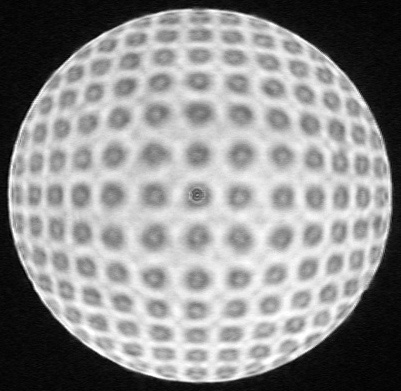 h zone each wire falls in? Works either way, right?
Here is a Spot Grid image of my 22" f/4.5 paraboloid mirror (right). This photo uses a homemade Spot Grid with 71 spots per inch in a square pattern. Each spot is ~0.005" diameter. The light source is a blue led shining through a 0.005" pinhole. I used a 640 x 480 pixel ccd camera with a 26mm Plossl eyepiece as the camera lens. The camera is hardwired into my computer.
Each shadow of a spot has a bright diffraction spot in the middle of it. Diffraction between the spots is minimized by the size of the pinhole and the distance between the spots in the grid.
This image is not yet good
enough to do the job, but it does illustrate the principle. For example,
you can see how the rows and columns of spots all bow outwards, like in
the example above. This is a paraboloid Newtonian telescope mirror, and
the grid is inside the radius of curvature. If you look at the eight spots
surrounding the center spot they form a square. The sides of the square
actually bend inwards slightly, instead of outwards (look at it from the
side). That is because this mirror has about an eight inch diameter 'hill'
in the center.
That hill is about a quarter-wave error on the wavefront. Some people will say that it is a good mirror. And 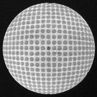 yet this photo allows a mere human to see the error first hand. And better resolution is achievable. I expect that a robotized version of this tester will give all the precision required to figure an excellent mirror. Soon any modern atm can make a 2D point-and-shoot Robo-Tester. Just aim the tester and the mirror at each other and the computer tells you what the figure is.
I also made this 10-zone Spot Grid photograph of my 22" (left). You will notice some diffraction problems around the edge, but the Spot Grid is far less susceptible to these things than the Ronchi grating. I opened Adobe Photoshop and took the picture with the ccd camera connected to my computer.
I then used Photoshop to manually measure the positions of the spots, and fed the info into James Burrows' Sixtests. If you have his program you can download TEST 5.TXT and TEST 6.TXT (test 6 is from a 12-zone photo, put them in the same directory as Sixtests.exe, open the program, and select a file). This experiment agrees well with all of the other tests I've made on this mirror. So now I can do the test, although I don't know how accurately. I expect the accuracy level will increase considerably when I get the test robotized.