|
|
Here are some
methods which function either inside of, or outside of, the radius of
curvature.
_____________________________________________________________________________________
Spot Grid
test
|
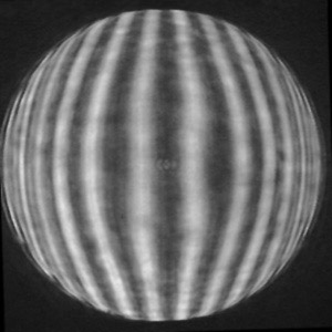
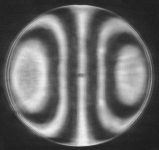
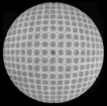
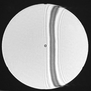
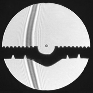
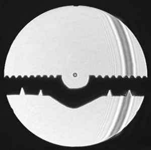
Next I'll show photographs I made of my 22" f/4.5 paraboloid Newtonian telescope mirror. These images were made using a blue led shining through a pinhole about 0.005" diameter. The first two images show the result of placing a 71 spi spot grid inside the roc. One shows six zones, the other shows eight. The rows and columns on the grid itself are straight, the aspherical nature of the mirror causes the lines to bend outward in the picture. The amount of bending can be measured, and so the mirror's shape can be figured out. These two images seem much more useful than the several corresponding images below them. |
|
|
|
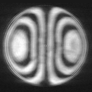
The biggest problem with the Ronchi grating is that the lines have severe diffraction interference problems. One of the tests described by Léon Foucault uses the two edges of a single wire. The Kent Wire test shown on page 2, with the Phi symbol, is done at the roc. Here I show a single wire used inside or outside the roc, the same as you'd use a Ronchi grating. The big advantage of a single wire is that its diffraction effects don't have the other lines to interfere with. So the line assumes the correct shape and is much easier to interpret. Although I am doing this differently than Foucault described, the result is similar. What I am doing is similar to the Lower test, done in reverse. The shape of the line is determined by the shape of the mirror at that point. If the mirror was a perfect sphere you could hold the line anywhere and it would appear perfectly straight. The lines should display smooth curves for a parabola, not that waviness like you see in these photos. This demonstrates how far from a parabola this particular mirror is. So we can look at the curve in the line and see the nature of the beast. In the left image the wire is inside the roc, and in the right image the wire is outside the roc. Both positions easily show the 8" diameter hill in the center of my mirror. The image on the right shows the bad turned-down edge as well. |
|
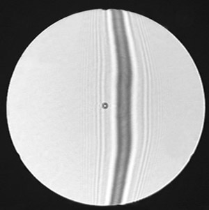
John Francis showed us a way to use the caustic test to quantify a single-wire test. He calls it the Lateral Wire Test (LWT). The red led with it's diffraction is also good for this test, and that is the light source used for this set of photos. Once again it provides a nice central bright division to mark the zones with. The LWT uses the single wire well inside the roc, and scans it from left to right across the mirror. Every time you reach a zone notch you record the readings. These two pictures show the line in the 4" zone on the left and the 8" zone on the right half. It is fairly easy to build a tester for the LWT, it is very easy to use, and it is the best way I have found to get data from near-spherical central zones. |
|
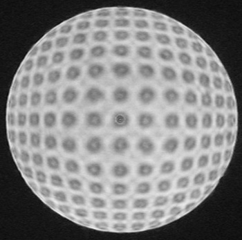
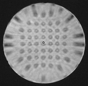
The two-dimensional version of the LWT is the LST, the Lateral Spot test, which is shown in the next image. Here you'll see a mask with zones (holes) everywhere across the mirror. The center zone has a dark ring which is the mark on the center of the mirror. To the left of that is a zone with a spot in it. The way you work the test is to record the settings, move the spot to the next zone, record the settings, move to the next zone, etc. until all the zones have been measured. This image was made with the blue led and the pinhole. 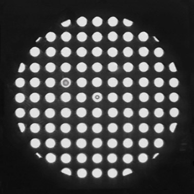 The Lateral Spot test is the 2D version of the Francis Test (LWT). The image on the left is what you might see when doing the LST. The way you work the test is to take an X and a Y reading, then move the spot to the next hole. Take another reading, move the spot, and so on. This is testing the whole mirror, instead of just one line through it. What could be easier? The Lateral Spot test is the 2D version of the Francis Test (LWT). The image on the left is what you might see when doing the LST. The way you work the test is to take an X and a Y reading, then move the spot to the next hole. Take another reading, move the spot, and so on. This is testing the whole mirror, instead of just one line through it. What could be easier? Well, building the tester and the software will be demanding, but using it seems simple. You can make a mask using your favorite mask-making materials. First cut out a disc the size of your mirror. You can use any hole pattern you wish, but you need to know the exact position of each hole. So it is best to use a stiff board, not a flexible wire screen. Here is one of the ways you can work the Lateral Spot test. Put the mask on your mirror, and be sure it is very well centered. It is best to use a very small spot. Neither the hole nor the spot necessarily have to be round for this test. If you are using monochromatic light and your spot is sufficiently small, then its shadow will appear as a diffraction pattern with a bright spot in the center. You want the size of the holes to be similar to the size of the shadow of the spot, so that you can line them up with precision. You compare the distance the spot appears to be from the center (optical axis) with the distance it actually is from the center. From this one can calculate the shape of the mirror. If you have astigmatism it is measured. Your spot is fixed to the base of the tester. The pinhole source is on an X - Y - Z mount. Set up so that the spot is a half inch or so inside the roc. The spot will be visible inside the reflection (just like a knife-edge would be). Now simply move the spot around in X and Y (X is up & down, Y is left & right, Z is towards the mirror). Now you can do the Francis Lateral Wire test in two dimensions! Line up the shadow with each hole in your mask and take a X/Y reading for each one (do not move in Z). Finish whatever pattern you use by double checking the first couple of readings you took. Rotate your mask some known amount and do another set of measurements, and feed them all into your favorite evaluation program. It spits out a 3-D result similar to what interferometry does. Done. |
Happy telescope
making!!![]()
![]()
![]()
![]()
![]()
![]()
![]()
![]()
email
copyright ©2002 -2004 by John Sherman