|
|
Here are some test methods which function at the radius of curvature with a single spot.
________________________________________________________________________
Spherical Spot test
|
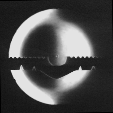
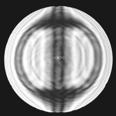
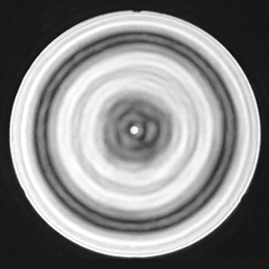
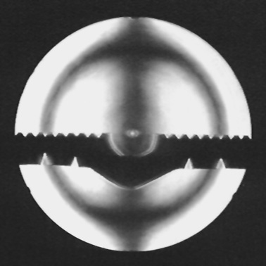
All you do is examine the image of a pinhole with a tiny spot. If you have a perfect sphere then the entire mirror is in the same zone. This causes the entire mirror to darken at the same time. Foucault t 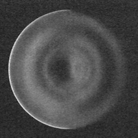 est users are quite familiar with this principle. A lot of surface detail can be seen in the null. This is not more sensitive than when using a straight knife edge, but using two dimensions improves the view because, if you have astigmatism it will be instantly visible. est users are quite familiar with this principle. A lot of surface detail can be seen in the null. This is not more sensitive than when using a straight knife edge, but using two dimensions improves the view because, if you have astigmatism it will be instantly visible.This test uses only a pinhole and a spot. The smaller the pinhole and the spot, the more sensitive the null will be. It is very low cost to make, and easy to setup and perform. You can move both pinhole and spot by hand. Here is an image of an 8" f/5 spheroid being null tested with a knife edge, the way Foucault described (left). Unfortunately my camera doesn't like the low light levels caused by the non-aluminized and spheroid mirror, and the dim led shining through the little ~0.005" pinhole, so these images 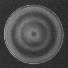 are noisy. It is probably best to back up and look at them from about ten feet away. The knife is cutting in from the right, so the surface of the mirror appears to be illuminated from the left. The mirror has a hole in the center and a big raised zone at the 60% radius (which looks like a donut). are noisy. It is probably best to back up and look at them from about ten feet away. The knife is cutting in from the right, so the surface of the mirror appears to be illuminated from the left. The mirror has a hole in the center and a big raised zone at the 60% radius (which looks like a donut).The next photo is the same mirror but now it is being null tested with a spot (right). The same zones are illuminated differently. Both sides are the same, and appear to be illuminated from the center. The big raised zone at about 60% radius is bright on the inside and dark on the outside. For this image I used a spot which is slightly larger than the pinhole. That means also that the spot is slightly larger than the image of the pinhole which the mirror forms.  So if you put this large spot exactly at the roc it would block all the light (except that you will still see diffraction effects). This image was made with the spot just outside the roc, so that some light can escape around the edge of the spot and be seen. Now, if the spot was moved just inside the roc, the big zone would appear illuminated from the outside in. Just as in the left half of the top image. So if you put this large spot exactly at the roc it would block all the light (except that you will still see diffraction effects). This image was made with the spot just outside the roc, so that some light can escape around the edge of the spot and be seen. Now, if the spot was moved just inside the roc, the big zone would appear illuminated from the outside in. Just as in the left half of the top image.The third photo is also the same mirror null tested with a spot (left). This time the spot is about half the size of the pinhole. That means the spot can be placed exactly at the image of the pinhole, and since it will be smaller than the image then about half of the light will still get past. The same zones can be seen, but the contrast is less. Very tiny spots are the most sensitive, but generally require a true point source of light to maintain good contrast. |
The Spherical Spot test is wonderfully sensitive because it is a null test. This means that when you do the test every part of the mirror is (supposed to be) at the same zone. Any part of the mirror which is at a different zone stands right out. You can get the same results from a complete telescope by using a real star as the light source.
Now I'll show three methods which work at the roc of an asphere. These photographs are of a 22" f/4.5 paraboloid mirror illuminated by the blue led shining through the ~0.005" pinhole. The purpose of these methods is to determine the relative length of the roc of each zone on the mirror. The data can then be combined to determine how far your mirror is from the perfect parabola, or whatever shape you're trying to achieve. |
________________________________________________________________________
________________________________________________________________________
| Here are some tips on spot-making: First, examine your pinhole with a very strong magnifying glass, like, a loupe or an inverted 25mm Plossl eyepiece will do. Make sure it is very round and clean, you don't want any burrs, etc. (You cannot use a slit light source as the test would then be constrained to one dimension.) The hole could be about 0.004" diameter (1/250 inch). The hole can be much smaller, but diffraction effects can become annoying. Now acquire a thin piece of glass, like, a microscope slide. Tiny spots can be made by very lightly misting with a can of spray paint. The spots should be perfectly round and about 0.004" diameter or so (0.1mm). There should be a variety of sizes, you will experiment with all of them. One of the sizes will be just right for the test you're currently running. I start with the glass several inches inside the roc, where it is easy to find. I bring the glass closer till I can see the small spots all over, then just move the glass over to center a spot I like. It's normally best to have the spot on the side of the glass facing the light, away from your eye. To measure diameters I have a machinists ruler with increments down to 0.010". Each line and each space between the lines is 0.005". Some of my spots are so small that I can barely see them with the naked eye. They are mere specks, about 0.001" or so. You can pick up a tiny drop of liquid paint with a small nail and make a big spot next to your favorite tiny spot. So far the smallest spots I've played with are the specks of dust landing on a clean glass slide. For spot grids I made a file in Photoshop and let the local camera store print the digital file directly onto slide film with their fancy machine. Please be careful!! Glass has sharp edges which can reach out and cut you. I don't want to hear of anyone shaving off their corneas or needing their noses sewn back on. As you may have learned from the Foucault knife-edge tester, it hurts when you cut yourself. |
Have fun, eh?
![]()
![]()
![]()
![]()
![]()
![]()
![]()
![]()
email
copyright ©2002 - 2004 by John Sherman

 or smaller. Every time the ring is centered on a zone I record the distance from the mirror for that zone. From this data the shape of the mirror can be determined.
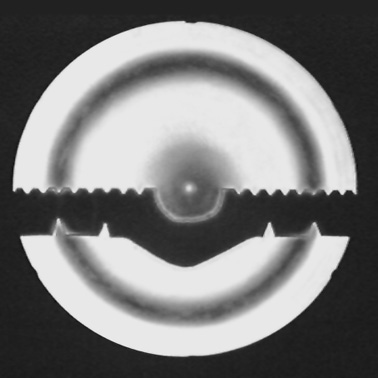 spot, which causes the dark ring shadow, and the out-of-focus spot itself blocks the center (right). The spot has an edge pointing in every direction, meaning that it is working in two dimensions. Light from the inner and the outer zones all get past the spot, only the 8" zone is blocked. The test is performed and reduced the same as the tests above.